Home | FAQ | CAE News | Contact Us

The Custom Shop
Building a Pedalboard Using a CAE Pedalboard Switching System
![]()
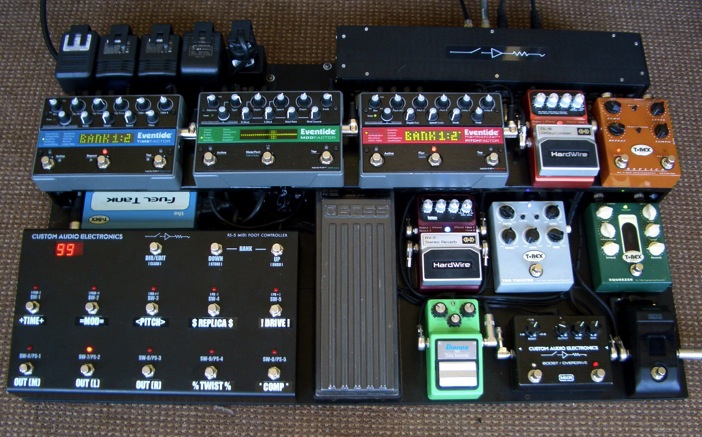
The objective of this project was to design and build a “system” using the new CAE Pedalboard Switching System controlled by a CAE RS-5 Midi Foot Controller. I believe this to be the best way to achieve “rack system” power and flexibility in a “pedalboard” format. I also wanted to feature the Eventide “Factor” pedals, as I feel these are some of the most powerful, full featured pedals available today. In addition, I wanted to try out some pedals from my friends at T-Rex and Digitech, along with some old favorites.
In this project essay, I will describe what it takes to design and build a board like this, and I will explain in detail why I chose to do things the way I did. I will explain signal path and what I wanted to achieve with the pedals I chose. And I will include a description of the new CAE “Pedal Lifter” supporting system, a handy way to raise and organize your pedals on a flat surface style pedal mounting board.
So put your helmet on,buckle up, and lets take a look at just what it takes to design and build this system! And just so you know,most of the information contained herein applies to rack-based systems as well…
DISCLAIMER ALERT!
This is a CAE demo system. This means I like to use “parts on hand” or stuff I have “laying around”. Since it is my rig, you will see parts or items used that I wouldn”t necessarily use with a paying customer. For example, I have tons of cables here that have been used in various systems throughout the years. I will re-purpose (ie: cut down and re-fit) these cables throughout this system. Suffice to say, If I were building a system for you, I would use all new stuff. I typically use Mogami 2524 and 2319 for the systems I build. So you will see a mix of both 2524 (the bigger diameter cable) and 2319 (the smaller stuff) on this board. FYI, I usually use 2319 for pedalboard wiring.
The Initial Concept
The Heart of this system is the CAE Pedalboard Switching System, hereafter known as the PSS. It pumps the blood (your signal) throughout the rig, and is controlled by the Brain, the RS-5 Midi Foot Controller.
It is up to you to tell it what to do.
CAE PSS systems are Custom Built. That is, you consult with me, and we determine exactly what it is you require. No two are the same. Sure, they utilize similar “building blocks” but the signal path (the way the loops are arranged) is totally unique to your requirements. This way you get exactly what you need in a high quality professional package.
Contact me via here for details.
For this system, I am utilizing a demo system I had built already. Therefore, I had to work within its fixed configuration (see Block Diagram). Actually, there were a few things I may have done differently, but I opted to work within these minor “limitations”. If this were your system, you wouldn”t have to worry about this! We would make it exactly the way you want it, within reason, of course.
For example, all PSS rigs with transformer isolated input/outputs utilize CAE ISO jacks, which include both Phase and Ground Lift switches for the ultimate in interfacing flexibility. This demo system DOES include the ISO jacks, but without the Phase and Ground Lift switches, as the prototype chassis used in this system was older and did not include the cutouts for the switches. Plus, I knew the application for this system, and therefore knew they weren”t absolutely necessary.
I will explain the various features of this particular PSS throughout this article.
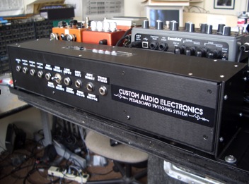 | 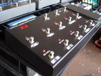 |
| The CAE PSS, aka “The Switcher” | The CAE RS-5 aka “The Foot Controller” |
PSS Description
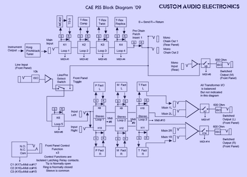
My “demo” PSS has 5 mono and 3 stereo switchable loops, 3 switchable outputs (Mono, Left and Right), a selectable Line Input/Pre option, as well as a stereo summing (mixer) output stage. Also included are 3 control functions for amp channel switching, and various “patch points” for interfacing between loop sections. Switching is done with passive relays, and buffering, or any active electronics for that manner, is kept to a minimum. The switched outputs (and Line Input ) are transformer isolated (via CAE ISO jacks)to prevent ground loop hum. Phase integrity is maintained throughout the system.
The Line/Pre switch effectively cuts the system in 2 parts. The first part is the mono “front end section” that starts at the system input, and ends at the mono switchable output via CAE ISO jacks. In between are the 4 mono switchable loops. There are also 2 different “patch points” which allow you to insert devices into the signal path if necessary. This could be anything from tuners to wah/volume pedals, or anything else. These inserts are passive,so you need to beware of what you put there as they are not switchable, so anything you put there is always in the signal path. In this system, I chose not to put anything there. See Block Diagram for details.
The second half of the system is the “Line in section” aka the “Post (or stereo) Section”. When the Line/Pre Select switch is in “Line” position, signal present at the Line In jack is transformer isolated, buffered, then feeds a mono switched loop (#5) then a patch point insert which then splits to the 3 stereo loops in series. The output of stereo loop #3 then feeds a stereo summing mixer section which in turn feeds the Left/Right switchable outputs via CAE ISO jacks.
When In “Pre” mode the signal present at the system input travels thru the first 4 loops and inserts, and is then buffered. Then the buffer output splits to the mono switched output and on to the post section mono loop #5 input. The switch basically bypasses the Line Input transformer and buffer, which is not needed in “Pre” mode.
So therefore, “Pre Mode” (the switch in the “pre position”) allows you to feed the inputs of 3 amplifiers, considered Mono, Left, and Right. Obviously, what effects are placed in the loops will determine what amps “see” what effects. The amps connected to the Left/Right outputs “see” all the effects in the system, and the amp connected to the “mono” output “sees” just the first 4 loops, or the “mono” chain. This could be considered the “dry” output in a wet/dry/wet configuration. The “Line mode” (the switch in the “line position”) allows you to feed line level signal (for example from an effects loop send or preamp output) into the stereo or “post ” section which splits that signal into stereo . A stereo power amp could then be connected to the Stereo Left/Right outputs. Or just another pair of amps considered stereo “wet”.
THE PSS BLOCK DIAGRAM
Determining Board Size
I decided to work within a fixed board size, which sets limitations on which pedals I could use. But first you have to determine what the system has to do for you in order to select the pedals you want to use. This is extremely important. Plan this out carefully, and take your time. As explained before, I already knew some of the pedals I wanted to use, (Eventide, T-Rex, etc,) and I knew the PSS/RS-5 would be used so that already started to determine the size. I settled on 34″x20″, which I felt was reasonable. This was also the side by side size of two of my old 3+ Preamp covers, (17″) which I used as a top surface of the board. I used 2 more (overlapped) to get the 20″ deep dimension. I used these on the other demo board I did.
For paying customers, board size is determined by what you need to use, no matter what, but size is a big factor. Sometimes board systems are split in two, to accommodate size/weight limitations. See example photos at the end of this article.
What Pedals to Use?
I now knew the board size. Now it is time to determine exactly what pedals to use, based on this knowledge. The 3 Eventide “Factor” pedals were a given, and I knew I wanted them in a row. I also knew I wanted the PSS in the upper right, as that is where it is designed to go. I have put them in other spots on other boards, but with experience I am finding upper right had corner (looking down at the board) to be the best bet. I am not a big fan of the “loop strip” idea (yes, I have designed and built them and do realize they have a purpose) as I feel cables plugged into a strip at your feet makes for a cluttered, messy approach.I prefer a two part system, foot controller at your feet where it belongs, and a audio interface at the opposite (audience) side of the board. This way, patching to amps and anything else “off board” is done on the “front edge” and pedal patching is done on the inside of the audio interface, “in the board” and facing you. This way you can clearly see the pedal patching, and outside cabling does not come “into” the board. I DO expect the CAE Pedal Lifters (more on these later) to help with the “Loop Strip” approach, and will report back if and when I change my tune on this matter.
With the PSS in the upper right, the best spot for the RS-5 foot controller was the lower left corner of the board. This way, cables to/from the pedals just to the right of the RS-5 would patch directly up to the loop send/returns of the PSS. Nice! The upper left corner of the board would be for power supply stuff, as far a possible from the PSS audio.
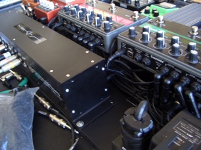
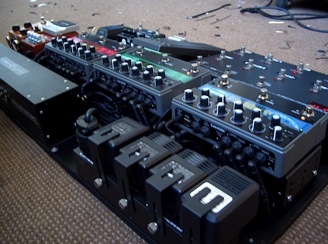
In the middle of the board would be the strip of Eventide pedals, along with a few others. These would be elevated using the new CAE Pedal Lifter support brackets. These are heavy gauge aluminum panels that allow you to elevate or “lift” selected pedals for better access, and to allow items to be fitted and secured underneath. This is very handy when trying to maintain a tightly spaced surface mount pedalboard with as small a footprint as possible.
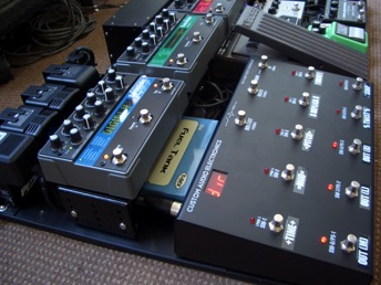 | 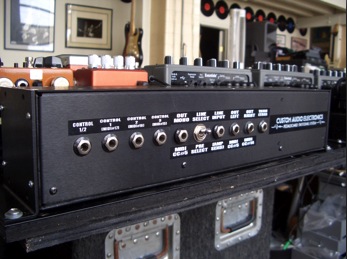 |
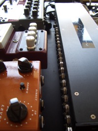
| The left side of the board. Note the Eventide pedals on the CAE Pedal Lifters, with power supplies left & right. | The front side of the PSS. This is where amps and other “outside world” connections are made. |
Ok, so I knew the Eventides would be in there, in stereo, so they are in the 3 stereo loops in this order:
PitchFactor first, then ModFactor then TimeFactor last. Here is where it gets a little interesting. I wanted the Pitch and Mod in series, in-line bypassed. This is because of the nature of their effects. If I want something 100% wet here(such as tremolo, panning, pitch effects, etc) I can do it. Or I create a balance within the effect itself, as usual. But the TimeFactor I wanted to mix in (or blend) with the signal present at its input.This way, when I bypass it, the echos trail off naturally, plus I am not running thru the unit for my original sound. I just connect the inputs to the loop sends, and connect its outputs to the PSS output section mix inputs, in stereo. And the PSS Send/Return jacks are simply half normalled, allowing this “split” to occur. You can then go into the TimeFactor and kill the dry path. The TF “mix” control then becomes effect output level. And programmable, of course. I wish all time based effects manufacturers made this so easy!
I wanted some form of volume pedal, so I used an old Boss FV300L (the low impedance version) that I had “laying around”. It is patched in mono to what is considered the “Line” or “Post section just before the “stereo split”. And for the “stereo split” I opted to use a pair of the Digitech Hardwire series pedals, the DL-8 Delay/Looper and the RV- 7 Reverb. These things are quite amazing. They are heavy duty, and sound great. The RV-7 is Lexicon Reverb in a pedal! They a have some special stuff inside that allows line level signal handling from a 9v power source, and as their name suggests, have 100% hardwire bypassing. Very cool. I had space on the board, and a place to patch them in (the DL-8 first, mono in from the volume pedal output) then stereo to the RV-7 Reverb, then stereo to the inputs of the Eventide/PSS bypass loops. I didn”t feel I needed to put them in switchable loops, as they “hardwire” bypass, and I tend to consider reverb, when used at all, to be set-and-forget anyway. The DL-8 delay was just for fun…wtf….Also, I didn”t need the mono loop 5.
I now had to consider the mono “front end” path. I only had switched 4 loops to work with here so I had to choose carefully. I knew this was going to be a mainly time-based effects board, but I needed at least a couple of overdrive type things. After careful consideration I chose the CAE/MXR MC402 Boost /Overdrive (duh!) and the old standby, a box stock TS-9 Tube Screamer. I like this combination, used together or separately, so they both went into Loop 1, with the MC402 being first. This way I could jam the TS-9 a little harder with the clean boost of the MC402.This works great.Try it. I chose a T-Rex Squeezer tube compressor for Loop 2.This is a fun little pedal with lots of tweek-ability, and therefore lots of different sounds. I wanted it in Loop 2 for the same reason the TS-9 comes after the MC402. The clean boost of the MC402 can jam the threshold of the compressor harder thus getting a different compressor sound, since it comes before it in the chain. Very handy. While we are on the subject of T-Rex, I used a Twister Chorus/Flanger in Loop 3,mainly just for fun to get some wacky warbling going on. It could be the first to go, who knows… And last but not least, The T-Rex Replica delay in Loop 4. I know there is a lot of delay stuff on this board (so sue me, I like delays) but the Replica is one of the best to me. It just has a great sound, and works extremely well in the front end of an amp, which is where it comes in the signal path of this system.This way, even the “dry” mono out can get a little wet if needed.
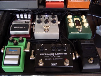 | 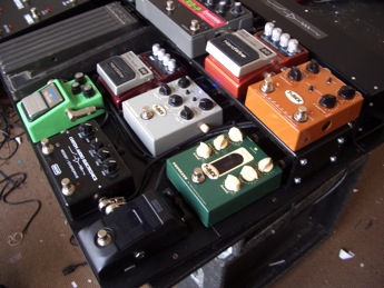 |
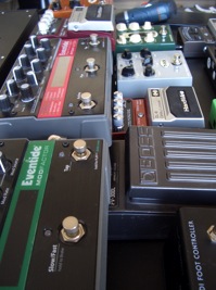
| The “Front End Stuff” (and their neighbors) | Another view of the “Front End” |
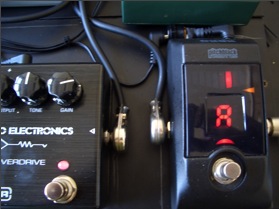 The only thing left to complete the signal path was a place to get into the system, and I wanted to do this with a tuner on the lower right hand corner of the board.Originally I planned to use the Digitech Hardwire Tuner, which is a fine unit, very heavy duty and accurate. However this didn”t work out. More on this later. I ended up with another great device I have used before,the Korg Pitchblack. I wanted a passive 100% bypass unit here, as it is a critical place in the signal path,and I wanted a mute-to-tune feature,so the Korg fit the bill.
Positioning and Placement
Now that I know what is going to be on the board, its time to fine tune placement.
I build what I call “surface mount” pedalboards. Always have. Everything mounts on the top surface of the board.I have seen some pretty cool boards, with false bottoms, compartments underneath, blah, blah, etc, etc…Thats all just fine, but I want quick access to all connections. I want to be able to see most connections, especially in case of emergency. The other issue is weight. All that fancy hidden stuff gets heavy. And these days, if you want to take it on a plane with you, It better be under 70lbs, or its going air cargo. Over 50 lbs,and you will likely be charged excess baggage, but at least they will take it. Over 70lbs? Forget it.
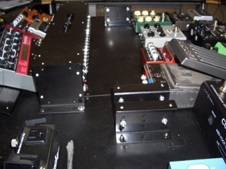
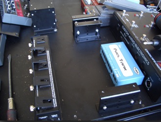
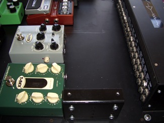
So I developed what I call CAE “Pedal Lifters”. Nothing fancy, just a simple support system that allows you elevate your pedals by fixed increments off of the flat pedalboard surface. They are made from heavy gauge aluminum, are powder coated black, and come in 3 lengths, 12″, 16″ and 20″. They are 4″ wide, and can accommodate almost any pedal known to man. And they don”t bend when pressure is applied. There are 2 different bracket heights,the tallest allowing a minimum height of 2.75″ and a maximum height of 4.25″ in .5″ increments.The smaller bracket allows a minimum height of 1.75″ and a maximum height of 2.25″. in .5″ increments. With the CAE Pedal Lifters, you can create a tiered pedalboard of various heights, and you can hide your power supplies, non critical boxes and messy wiring using a simple flat surface pedalboard! Get a slab of 3/8 Plywood at Home Depot, a can of black spray paint, a bunch of Pedal Lifters, and look pro in no time. Or get a nice laminated board from A&S Case Company and attach the Pedal Lifters to it.They attach to the board with either 10-32 machine screws via holes drilled in the board (screwed in from the bottom,the preferred method) or you can sink #8 wood screws in from the top.
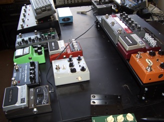 | Here we are formulating a placement plan. I suggest you take your time at this point, as things can change quickly once you give it some thought. Try to let it sit at least overnight. You”d be surprised what can change. Note the pedals sitting on the “Lifters”. |
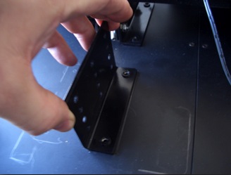 | 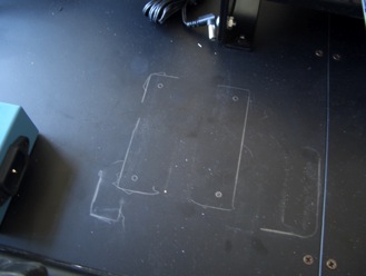 |
| You can use the Pedal Lifter bracket as a template to mark your hole pattern. | Pedal Lifter bracket holes ready to be drilled. |
 |  |
| Pedal Lifter brackets installed. | Installed Pedal Lifter brackets. Note power supply positions. |
 | 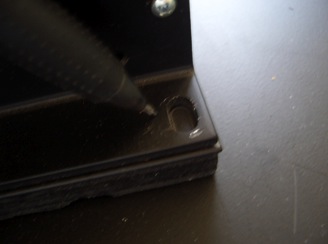 |
| Note position of pedals to bracket/PSS. | The PSS gets bolted down as well. Look closely…yes, those are rack ears. You can rotate them 90 degrees and rack mount the PSS! |
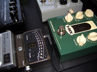 | 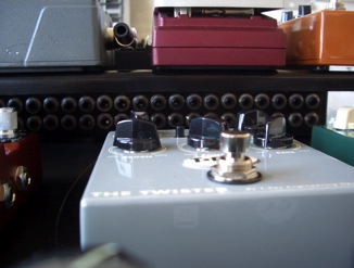 |
| Pedal positioning is critical at this point. You have to allow room for all connections. | Note that the Pedal Lifter height just clears the PSS top jack row. Yes, this was intentional! |
|
|
|
|
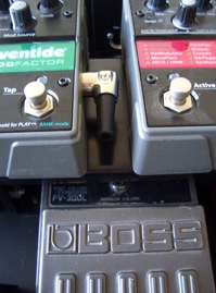
| Straight midi connectors can take up valuable space. Right angle connectors are expensive, but worth it. | Straight cable connectors are needed on the PSS, but right angles can be used on the pedals above, to save space. | Right angle connectors will be used on the Eventide pedals, as their power supplies have yet to be installed on the Furman Plug Lock Power Strip. |
|
|
|
| Note the line up of pedals below to the pedals on the Lifters above. The Boss volume pedal can tuck up underneath the Lifter, saving space. | Right angle connectors were definitely needed on the Eventides to clear the PSS! |
Pedalboard Power Supplies
Power Supplies are a necessary fact of pedal board life unless you can run everything on batteries, which is unlikely and impractical anyway.Power supplies take up space, and if improperly positioned can cause unwanted hum and noise. I try to keep power supplies away from critical audio paths as much as possible. In this system I elected to place the power supplies in the upper left hand corner, and under the Pedal Lifter that holds up the TimeFactor and ModFactor, just in front of the RS-5. This turned out to be pretty convenient, as audio going to/from the TF and MF is generally closer to line level (unless I am running in a “front end” configuration). As it turns out, the noise performance was quite acceptable here as well. I decided to use a T-Rex Fuel Tank as the 9 and 12vdc pedal power supply since it had the necessary voltages to power their pedals as well as the other pedals I decided to use. The CAE PSS/RS-5 combo required its own supply, as well as each of the Eventide pedals. I could have built a fancy all-in-one power supply for the CAE and Eventide stuff utilizing low noise torroid power transformers, but I wanted this system to reflect a more real-world approach, so I used the supplies that came with the Eventides and a typical 9VAC wall wart for the CAE system, all tied together with a Furman Plug Lock AC power strip. The Furman “brackets in” all the wall warts, and prevents them from becoming unplugged. A nice touch. The Fuel Tank connects via a standard ac power cable with an IEC connector. I used an ac Y cable here in case I ever need to connect some other ac powered device, as the Furman has only 5 outlets and I used them all.
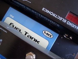 |  |
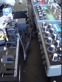
| Here is the Fuel Tank positioned next to the RS-5 and under the Time Factor. | A bunch o’ wall warts securely clamped down. |
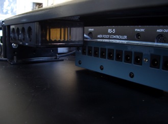 | 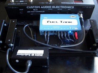 |
| Here is the Fuel Tank hiding under the Pedal Lifter. Thats a midi thru box tied to the roof to the left of the “Tank”. | The Fuel Tank up and running.That is the RS-5 xlr control cable to the right of the “Tank” |
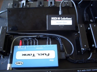 | I opted to use a Midi Solutions Quadra Thru Box to distribute midi signal to each Eventide pedal individually, rather than utilize each pedal”s thru connection. This is a more reliable approach to midi signal distribution, and since it is a split,any pedal can be removed without disturbing the midi signal path. |
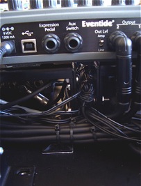 | 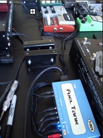 |
| I bundled up the excess cable lengths from the Eventide power supplies, and tucked the excess cable between the Pedal Lifter”s support brackets. Not the cleanest approach I know, but I didn”t want to cut down the cable length, as these pedals may be called into service elsewhere in the future, and I may need the length then. | I ran power cables from the Fuel Tank supply to the various pedals using pre-existing cable that comes with the power supplies. |
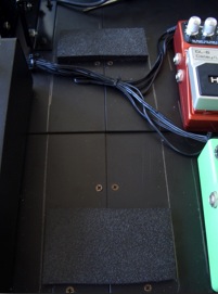 | 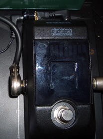 |
| Since I was using pre determined lengths of power cable rather that custom lengths, I had to run the shortest path possible. Therefore, I had to raise the volume pedal slightly with wood blocks in order to run the power cables underneath. | *Note Ground Lift “adaptor” |
Originally I had planned to use the Digitech Hardwire Tuner, but when I fired up the system to audio test, there was an unacceptable hum. The T-Rex Fuel Tank does not have individually ground isolated 9vdc outputs, and when I disconnected DC power from the tuner, the hum stopped. I then tried dis-connecting the ground (-)* on the power cable, but the Digitech tuner did not like that. So I tried the Korg Pitchblack, which didn”t have a problem with the lifted ground. Problem solved. Quiet system.
Wiring/Assembling The System
System wiring can be an art form unto itself. Neatness counts here.There are tons of different cables out there to choose from, a lot that are very good, and some that are….well….not so good. A lot of ink has been spilled regarding cable over the past few years, a lot of it good practical knowledge based on experience, and a lot just plain hype. It is my contention that the most critical link is between a guitar”s output (assuming passive pickups, of course) and the input of the first active stage the guitar”s signal hits. After that,all bets are off.Most good cable will sound the same (to most normal humans at least)after that first active stage, whether its a “buffer” or some distortion box, or anything for that matter. Sure, some people swear they hear a difference just plugging in a wah pedal bypassed, all other things being equal. I”m not talking about them,I”m talking about us!
As a system designer (with ears BTW), I am sensitive to these issues, and go to great pains to insure the sonic integrity of my systems. I use great cable, and my cable of choice is Mogami. I have been using it for years, and I like the way it sounds, and second, I like the way it preps. Its easy for me to work with. And along with great cable, I utilize as little active circuitry (aka “buffers”) in the signal path as possible. To me, active “buffer” circuitry is a necessary part of a modern guitar system, but they have gotten a bad rap over the years,mainly due to misunderstanding their actual role in a system. See our FAQ for more info on “buffers”. So I say use ‘em (designed as high in quality as possible), but only where absolutely necessary. That being said, the PSS used here has no active circuitry until after the first 4 Loops and the patch point inserts associated with the mono Loop chain (see Block Diagram).
I have said this before, but it bears repeating: putting your effects into a CAE Loop based system is the cleanest, most sonically “pure” way to get through a series chain of pedals, because
when you bypass the pedal, you are bypassing the cables connecting the pedal as well! Notice I said “CAE Loop Based System”. CAE Loop chains are generally internally connected together in a series configuration, mainly to save on jack count, and to provide a purer signal path with minimum outside connections. Not so with other manufacturers. With them, (trying to be all things to all people and cover as many scenarios as possible) you will have to connect each loop together with a cable (!) in order to create a series signal chain. Not good. With a CAE system, we determine your unique signal path via consultation with you personally, and do as much internal wiring as possible (but still allowing for “patch inserts” where necessary) thus improving signal integrity and reliability.
So in this system, the first thing the guitar “sees” is the Korg Pitchblack tuner, a passive device when bypassed, BTW. Then it is on to the system input, aka Loop 1 in. The previously chosen pedals are wired into the first 4 Loops (see “What Pedals To Use” on page 4). Then the Boss FV300L Volume Pedal/Digitech Hardwire DL-8 Delay/RV-7 Reverb combination is wired to the PSS insert “patch points” at the appropriate spot in the signal path. See Block Diagram for details.
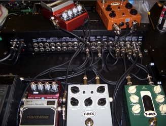 | 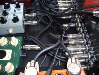 |
| Neatness counts here as much as possible,as this area is going to get very crowded with cable. | Its a good idea to cable tie associated cables together to maintain some organization. |
Next comes wiring the Eventide pedals. 3 stereo pedals….12 cables…its getting crowded! Normally I would have used the smaller diameter Mogami 2319. This would have saved a ton of space, and made things less crowded, but remember what I said before about “parts on hand”? Cable ties can really keep things manageable here, so use a bunch. You won”t be sorry.
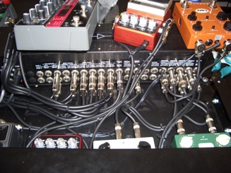 | 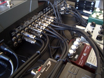 |
| As neat as you try to make it, it can still look messy so try to keep it the cables as organized as possible. Luckily the Cable Lifter and pedals will hide all this! | Bundled Eventide pedal “looms.” Don”t skimp on the cable ties! |
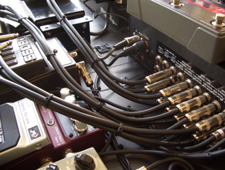 | 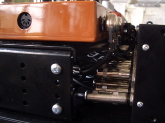 |
| Note the cable tie mounts on the board waiting for the Eventide cable bundles. Use these judiciously as well to maintain orderly cable routing. Use a wood screw to attach them to the board, as the adhesive will eventually give out. | The Pedal Lifter and pedals in place. See? Careful planning makes for a tight yet clean arrangement. Need to change patching? Just pop the pedals loose that cover the Lifter”s mounting screws then lift up to expose the wiring underneath. Simple. |
Fasteners
I typically secure the pedals to the board with 3M Dual Lock, usually SJ3560. This is the clear stuff adhesive backed in 1″ widths. You could also use Velcro, and here I would suggest 2″ widths. With Velcro, you need both hook and loop, but with Dual Lock, only 1 “sex” is needed, as it fastens to itself. You can get Dual Lock and Velcro from www.fastenation.com. Another handy adhesive I have been using for years is GE Household Glue. It is a clear silicone glue and works great on just about any surface. It peels away easily when not needed as well.
The CAE RS-5 Midi Foot Controller
Now we need a foot controller to access the loops in the PSS, and of course the CAE RS-5 Midi Foot controller is the perfect choice for this application! I will explain the features of the RS-5 as they pertain to this system.
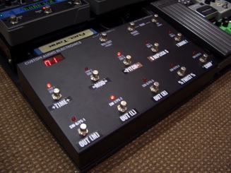 | 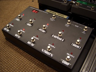 |
The RS-5″s smaller “footprint” (as compared to its bigger brother, the RS-10) makes it a welcome addition to a pedalboard based system. The smaller footprint comes at a price, however. In order to save space, the RS-5 shares 5 of its footswitches (the bottom row) between “Direct Mode” and “Preset Mode“. In “Direct Mode” you have 2 rows of 5 “Direct Access” controller switches. These are the switches (aka Instant Access) that are assigned to control the Loops, Switchable Outputs and or Control Functions in the PSS. Each of these 10 switches is programmed a unique midi cc# that each function in the PSS needs to “see” in order to work. No 2 switches should have the same midi cc# assigned,otherwise a conflict will occur when using RS-5 Presets. When in “Preset Mode” the bottom row of switches become random access (mutually exclusive) “Presets”.
A “Preset” in the RS-5 consists of a pre-programmed combination of the 10 Direct Access controller states, as well as up to 4 separate (user programmable) midi Program (aka patch) Change commands sent on 4 separate midi channels. The middle row of Direct Access switches remain Direct (instant) Access at all times.
It is important to know that in the RS-5, 10 Direct Access midi controller states are sent out (along with midi Program Changes)when a RS-5 “Preset” is selected, even though you don”t see the status LEDs change on the bottom row of switches!
This is because the bottom row of LEDs indicate 1 of 5 Presets selected in “Preset” mode. You can instantly check status of all 10 Direct Access controller states (Loops etc, on or off) by toggling the DIR/EDIT Switch (top row). When in “Direct Mode” the display will read “dir” and the combination of 10 Direct switch LEDs will be lit, depending on their status in the currently active Preset. When in “Preset Mode“, the display will read a 2 digit number indicating the current Bank status, and the rightmost digit shows the “Global Preset” status with a “-”, indicating that the “Global Preset” is active. The “Global Preset” is actually a 6th “Preset” containing all the midi information of the other Presets.The difference is, it is the same in all Banks, and can be considered a “home base” type Preset, and is accessed by pressing any active “Preset” switch. This way you can effectively access 2 Presets with the press of 1 switch! In addition, when in Preset Mode the currently active “Preset” LED will be lit.
Preset Banks are accessed via the Bank UP/DOWN switches. There are 100 Banks, 00 thru 99. Banks can be directly accessed or previewed depending on a user defined setting in edit mode. Banks can be limited as well. Any sequential number of Banks can be set, by determining a lower limit and upper limit in edit mode. One handy application,if you don”t need many banks, is to set the limit to 2 banks, with direct Bank access. This way, you have direct access to 10 Presets (2 Banks of 5 Presets) with a minimum of switch moves by toggling between the 2 Banks.
So now we know a little about Banks, Presets, and the meaning of Direct Access. Now we need to assign the 10 Direct Access controller switches to the functions in the PSS. Actually the PSS has more internal functions (Loops, etc.) than the RS-5 has controller switches, but of course I knew this when I decided on what effects and functionality the system was going to have, and chose 10 things accordingly. When deciding what RS-5 switch did what, I had to consider what was the 5 most important effects I wanted direct access to at all times, and programmed the middle row of the RS-5 these 5(left to right): The 3 Eventide Pedals, the T-Rex Replica, and the “Drive” loop, ie: the CAE/MXR MC402/TS-9 combination. I figured I would want to turn any of these on or off regardless of RS-5 mode. The bottom row (left to right) got the Mono,Left, and Right Switched Outs, then the T-Rex Twister,and finally the T-Rex Squeezer(Comp).
Here is another consideration and a cool feature of the RS-5: Remember, in this particular PSS, outputs are switchable. This means they must selected in order to hear anything.This is fine for a mutli-amp configuration where different amps are needed for different sounds (rhythm, lead, etc.) But sometimes I want a typical 2 cab “stereo” configuration with a preamp/power amp combination (with optional center “dry”). Therefore, I need all 3 outputs on all the time. Now I could certainly program all 3 outputs “on” in all the presets, but there is another way. The RS-5 allows the user (via edit mode) to determine which of the 10 “Direct Access” controller switches are “global”.That is, their status is independent of what the “presets” are doing.In other words, they can be set-and-forget, and don”t respond to Preset commands/combinations. This way I can turn on the outputs, and not worry that they will change when I use “Presets”.For me, the Presets in this system will mainly be used to change programs on the Eventides.
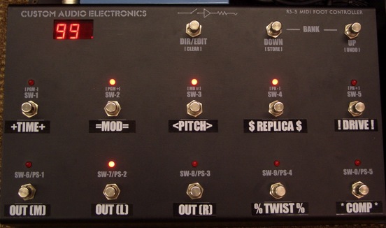
I labeled the switches with my trusty Brother P-Touch label maker, and I was good to go
The beauty of this system is not only the pristine audio quality, but the programmability, not only with preset combinations of effects, but the programability of the effects themselves, namely the Eventide “Factor” pedals. This is what makes a system like this so powerful. It certainly has the power and sonic integrity of my more elaborate rack systems, but with a little more portability. As stated before, the RS-5 can send up to 4 midi program change commands on 4 separate channels. Therefore, I assigned each Eventide pedal is own midi channel, and send each pedal separate commands from the RS-5. No midi mapping necessary. Midi program changes are sent only when needed, via the RS-5 Presets. I will post a video tutorial on this subject asap.
These days, there are many options when designing and building a professional pedalboard system. I know, I have nearly 30 years experience doing just this. But this is my take on the subject. And not the only one at that. Different choices/combinations of gear will produce different results, and I look forward to coming up with different systems in the future. Maybe one for you, with your choices.
Meanwhile, here are a few systems I have done, utilizing this approach. Enjoy!
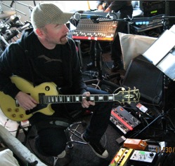 | Look close,just below the guitar headstock. This is a RS-5/PSS built as a multi-amp amp splitter for a guy called “The Edge.” I think he”s in a band called U2 or something… |
| This is for indie rock icon J.Mascis (Dinosaur Jr.) This is actually Version 1, as some pedals have been swapped out since its maiden voyage. Sometime combinations of pedals work better in theory than application and revisions must be made. J. loves his pedals and knows how to use ‘em. | 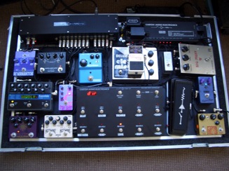 |
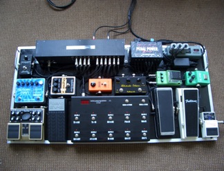 | Here is Jesse Johnson”s (The Time) board. Note the 2 wahs. The man is serious about his funk. Time (pun intended) to hook him up with a Dunlop/CAE wah! |
| This was built for my friend Benni Bilgeri, a “gun for hire” in Austria. Benni”s a lefty, which threw me for a minute… Note the awesome Dunlop/CAE Wah on the left. Input to the system happens via a “patchbox” under the Korg itchblack Tuner, which also raises the tuner for better foot access. Ergonomics, baby!
Check out the cool AC strip featuring IEC connectors in the upper right had corner. This was needed as this system is 230VAC | 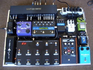 |
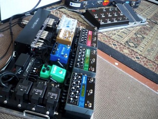 | This was for Benjamin Hazlett, who plays with pop songstress Colbie Caillat. Note the 2 board configuration. This was mainly due to size/weight restrictions for fly dates. And it came in under weight! This is a big issue these days. But not only that, this is a killer way to do a system like this. |
| This one is for Tad Kubler (The Hold Steady, an awesome live band!). This has multiple outputs for mutiple amps. Tad was blown away by the sonic clarity of the system.With all those Boss (active) pedals, I can see why. Here is where a passive signal path with minimum active electronics really makes a difference. I think Tad only uses this in direct mode, and has yet to get into Presets. In time, my friend, in time… This thing even drank a beer in London and lived to tell the tale. | 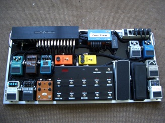 |
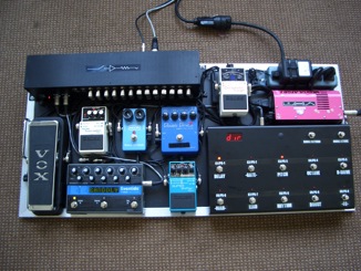 | This little rascal is for Page Hamilton (Helmet). Another “keep it under 50 lbs” rig for excess baggage fly dates. This thing gets brutalized by stage diving goons all the time. |
| This is for my pal Frank (Survivor) Sullivan. Frank has many systems from me, and this is the latest. This system can be configured in many different ways depending on what amps are used,and features 5 Switchable outputs. You can”t really tell here, but the Eventide pedals are angled for visibility. | 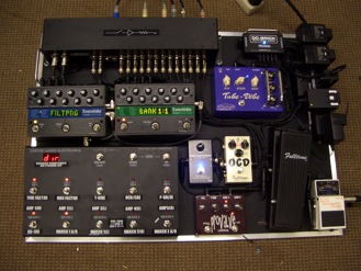 |
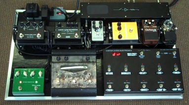 | This is for Warren Haynes, the hardest working man in show biz. (Govt. Mule, The Allman Brothers Band, The Dead etc…) This is the 3rd rig for Warren, and the first shipped with CAE Pedal Lifters. Notice how the boards are “tightening up” space wise, with the help of the Pedal Lifters. Yet another “fly date” rig. |
| This is for Alvin Hunt, a guitar lovin” attorney from Louisiana. Figuring this thing out inspired the design of the Pedal Lifters. Alvin pretty much gave me carte blanche to design this system any way I wanted. Its a real challenge to get a bunch of different sized boxes to fit together in as small a space as possible. My system (described here) came together after I built this. Look familiar? | 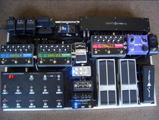 |
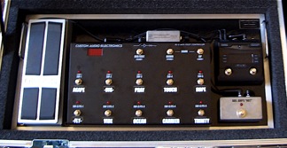 | 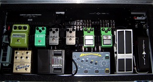 |
| This baby is a 3(!) part rig for Texas songwriter Ryan Tinch and is used primarily with acoustic guitar. You heard me, acoustic! Multiple amps (4) multiple effects, looping, Avalon preamp…this thing is built to thrill! Certainly a unique signal path. 2 boards, 1 rack. I hope to hear him use it one day. Boards are shown in their cases… | 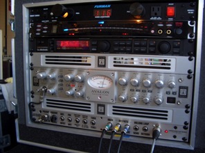 |
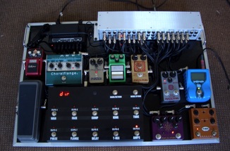 | And the one that started it all, (dig the prototype PSS) built for Rogers Stevens, of Blind Melon fame, as seen in Guitar Player magazine. I”ve since heard from Rogers that the band imploded (yet again) and he sold it off, and has gone back to school as a philosophy major…Good Luck Rogers…I still love you… |
